

Disclaimer
The community here at 355nation.net urges you to please use caution and seek professional assistance when performing modifications to your vehicle. Before attempting any modification it is advised that you refer to your Colorado or Canyon service manual or contact a certified mechanic as not all GMT355 trucks are the same. The staff and the associated members are in no way responsible for any damages, injuries or other harm inflicted to your vehicle or yourself which may result in attempting these modifications. The posts and content presented on this site reflect in no way the views of 355nation.net or it’s ownership.
![Image]()
A 355nation How To presented by
dents-n-dings
Project Name
Front Hub/Wheel Bearing Replacement
Project Description
Removal and Installation of Hub/Wheel Bearing
Skill Level
Moderate
Project Vehicle
Make: Chevrolet
Model: Colorado
Year: 2004
Engine: 3.5L
Power windows: Yes
Sun Roof: No
Tools Needed (in order of use)
Tire Iron
Wheel Chocks
Floor Jack
Jack Stands
Long Pry Bar or Axe Handle
Cheater Bar
35mm Deep Well
17mm Socket
3" Extension
Pliers
Screwdriver
21mm Socket
15mm Socket (3/8")
3/8" Swivel
Piece of Cloth
Block of Wood
Rubber Mallet
Grease
Project Time
3-4 Hours
Project Cost
~$200 Hub Assembly (GM # 25832144)
~$40 ABS Speed Sensor (GM # 15176997/Left; GM # 15176998/Right)
Symptoms
Rotational vibration/wobbling felt through the gas pedal, excessive shimmy/play in the tire when jacked up.
Procedure
Loosen lug nuts and chock rear tires.
Jack up the front end and place firmly on jack stands. Remove the wheel & tire.
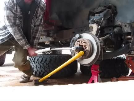
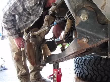
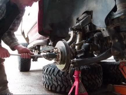
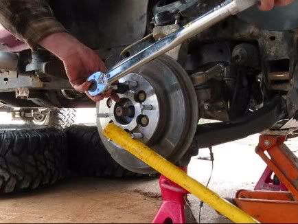
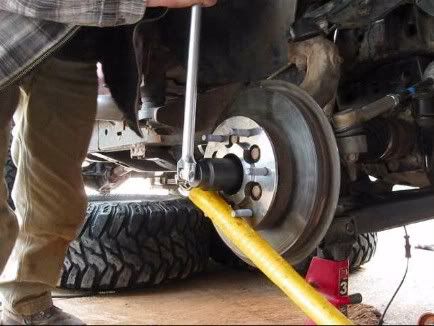
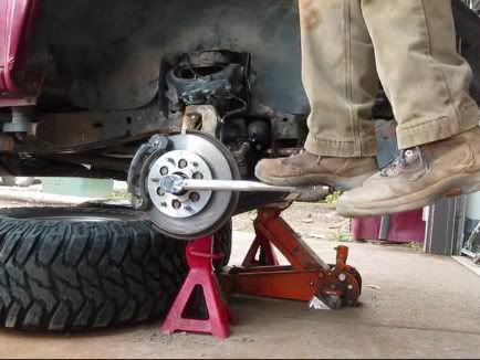
Place a pry bar or equivalent between 2 lug bolts to hold the hub from spinning. Loosen the hub nut with a 35mm deep well socket and cheater bar. If the nut is too tight, have someone hold down the brakes to loosen the nut.
![Image]()
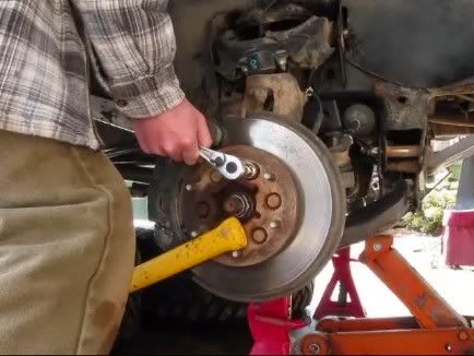
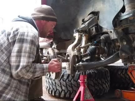
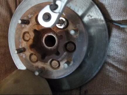
Break loose the (6) 17mm bolts that hold the brake disc to the hub. Leave these bolts in place until later.
![Image]()
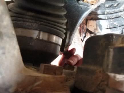
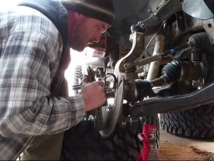
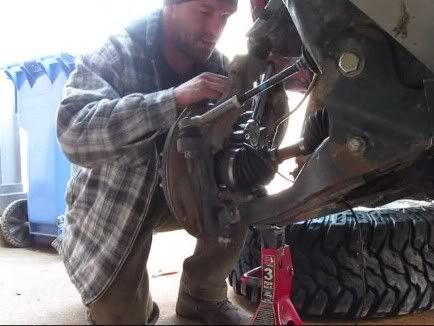
Using pliers & screwdriver, disconnect the ABS harness at the top of the wheel well, and remove the cable from the clips all the way down to the hub.
![Image]()
![Image]()
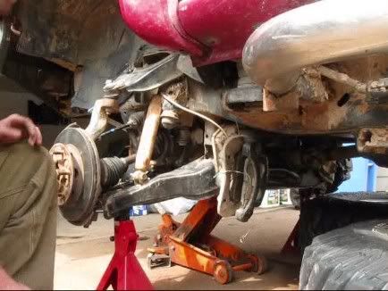
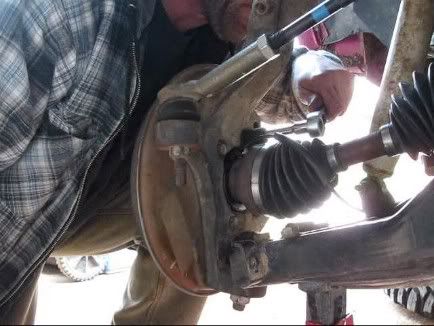
Remove the (2) 21mm bolts that hold the brake caliper to the spindle. Slide the brake caliper off of the brake disc and tie it off with zip ties/wire to the frame out of the way. Make sure the brake caliper is not hanging from the brake line.
![Image]()
![Image]()
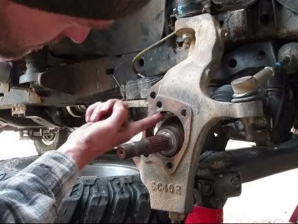
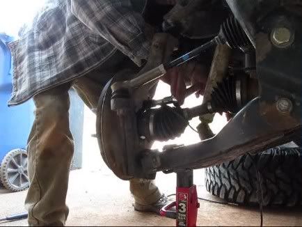
Remove the (4) 15mm bolts that hold the hub to the spindle. The bolt above the lower ball joint will require a swivel & extension.
![Image]()
![Image]()
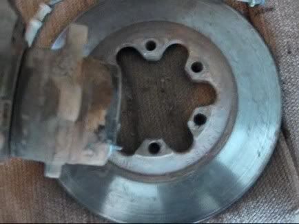
Remove the hub nut & washer, and pull the hub out of the spindle using a forceful, wiggling motion.
![Image]()
![Image]()
Place the hub on a soft surface to avoid damaging the brake disc. Remove the (6) 17mm bolts that hold the brake disc to the hub. Separate the brake disc from the hub.
![Image]()
![Image]()
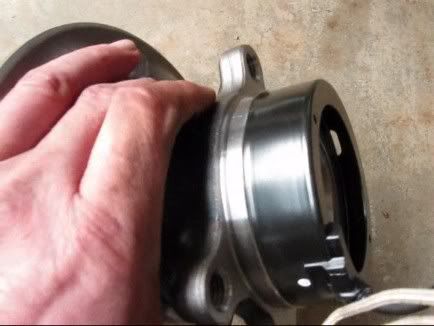
Place the new hub on a hard, flat surface with the lug bolts facing down. Note the ABS speed sensor position on the old hub, and press the new ABS speed sensor (left/right specific) down on the new hub in the same position. Using a piece of cloth and block of wood, gently tap the ABS speed sensor down on the new hub with a rubber mallet until it sits flush and even with the flange. Take your time and check the position frequently.
![Image]()
![Image]()
![Image]()
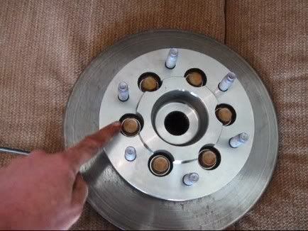
Place the hub on a soft surface, feed the ABS speed sensor cable through the brake disc, and join the brake disc to the hub. Make sure all mating surfaces are clean and flush. The thick side of the brake disc & the “min. safe thickness” text should be facing out toward the lug bolts. Install the (6) 17mm bolts and tighten them to 15lbs (snug), using an alternating/opposite torque pattern. These bolts will be tightened to torque specs later, when the hub is attached to the spindle.
![Image]()
![Image]()
Clean and lubricate the hole where the hub joins the spindle with a small amount of grease. Insert the end of the ABS speed sensor cable through the brake disc shield and spindle.
With the ABS speed sensor cable facing up, slide the hub onto the axle and into the spindle while carefully feeding the ABS speed sensor cable through. Use a rubber mallet and bad language to persuade the hub into the spindle until it sits flush. Make sure the brake disc shield is positioned correctly, then install the (4) 15mm bolts and tighten them to 15lbs of torque. These will be tightened to torque specs later.
![Image]()
![Image]()
![Image]()
![Image]()
Using a pry bar to keep the hub from spinning, tighten the (6) 17mm bolts that hold the brake disc to the hub to 88lbs of torque.
![Image]()
With the pry bar still in place, install the washer & hub nut and tighten just enough as to not cause damage to the lug bolts from the pry bar. The nut will be tightened to torque specs later, after the brakes are installed.
![Image]()
Tighten the (4) 15mm bolts that hold the hub to the spindle to 92lbs of torque.
![Image]()
Clean and wipe down the brake disc with brake cleaner and a soft cloth. Slide the caliper on the brake disc and install the (2) 21mm bolts that mount the caliper to the spindle. Tighten to 129lbs of torque.
![Image]()
![Image]()
Reconnect the ABS speed sensor wire to the clips, and plug the end into the harness. Reattach the harness to the wheel well.
Start the truck and have an assistant apply the brakes. Tighten the hub nut to 191lbs of torque.
![Image]()
Take time to double check torque on all bolts.
Install the wheel & tire and tighten the lug nuts in an alternating/opposite torque pattern until snug.
Lower the truck firmly on the ground and tighten lug nuts to 103lbs of torque.
Videos
The community here at 355nation.net urges you to please use caution and seek professional assistance when performing modifications to your vehicle. Before attempting any modification it is advised that you refer to your Colorado or Canyon service manual or contact a certified mechanic as not all GMT355 trucks are the same. The staff and the associated members are in no way responsible for any damages, injuries or other harm inflicted to your vehicle or yourself which may result in attempting these modifications. The posts and content presented on this site reflect in no way the views of 355nation.net or it’s ownership.
A 355nation How To presented by
dents-n-dings
Project Name
Front Hub/Wheel Bearing Replacement
Project Description
Removal and Installation of Hub/Wheel Bearing
Skill Level
Moderate
Project Vehicle
Make: Chevrolet
Model: Colorado
Year: 2004
Engine: 3.5L
Power windows: Yes
Sun Roof: No
Tools Needed (in order of use)
Tire Iron
Wheel Chocks
Floor Jack
Jack Stands
Long Pry Bar or Axe Handle
Cheater Bar
35mm Deep Well
17mm Socket
3" Extension
Pliers
Screwdriver
21mm Socket
15mm Socket (3/8")
3/8" Swivel
Piece of Cloth
Block of Wood
Rubber Mallet
Grease
Project Time
3-4 Hours
Project Cost
~$200 Hub Assembly (GM # 25832144)
~$40 ABS Speed Sensor (GM # 15176997/Left; GM # 15176998/Right)
Symptoms
Rotational vibration/wobbling felt through the gas pedal, excessive shimmy/play in the tire when jacked up.
Procedure
Loosen lug nuts and chock rear tires.
Jack up the front end and place firmly on jack stands. Remove the wheel & tire.
Place a pry bar or equivalent between 2 lug bolts to hold the hub from spinning. Loosen the hub nut with a 35mm deep well socket and cheater bar. If the nut is too tight, have someone hold down the brakes to loosen the nut.
Break loose the (6) 17mm bolts that hold the brake disc to the hub. Leave these bolts in place until later.
Using pliers & screwdriver, disconnect the ABS harness at the top of the wheel well, and remove the cable from the clips all the way down to the hub.


Remove the (2) 21mm bolts that hold the brake caliper to the spindle. Slide the brake caliper off of the brake disc and tie it off with zip ties/wire to the frame out of the way. Make sure the brake caliper is not hanging from the brake line.
Remove the (4) 15mm bolts that hold the hub to the spindle. The bolt above the lower ball joint will require a swivel & extension.

Remove the hub nut & washer, and pull the hub out of the spindle using a forceful, wiggling motion.
Place the hub on a soft surface to avoid damaging the brake disc. Remove the (6) 17mm bolts that hold the brake disc to the hub. Separate the brake disc from the hub.
Place the new hub on a hard, flat surface with the lug bolts facing down. Note the ABS speed sensor position on the old hub, and press the new ABS speed sensor (left/right specific) down on the new hub in the same position. Using a piece of cloth and block of wood, gently tap the ABS speed sensor down on the new hub with a rubber mallet until it sits flush and even with the flange. Take your time and check the position frequently.


Place the hub on a soft surface, feed the ABS speed sensor cable through the brake disc, and join the brake disc to the hub. Make sure all mating surfaces are clean and flush. The thick side of the brake disc & the “min. safe thickness” text should be facing out toward the lug bolts. Install the (6) 17mm bolts and tighten them to 15lbs (snug), using an alternating/opposite torque pattern. These bolts will be tightened to torque specs later, when the hub is attached to the spindle.

Clean and lubricate the hole where the hub joins the spindle with a small amount of grease. Insert the end of the ABS speed sensor cable through the brake disc shield and spindle.
With the ABS speed sensor cable facing up, slide the hub onto the axle and into the spindle while carefully feeding the ABS speed sensor cable through. Use a rubber mallet and bad language to persuade the hub into the spindle until it sits flush. Make sure the brake disc shield is positioned correctly, then install the (4) 15mm bolts and tighten them to 15lbs of torque. These will be tightened to torque specs later.

Using a pry bar to keep the hub from spinning, tighten the (6) 17mm bolts that hold the brake disc to the hub to 88lbs of torque.
With the pry bar still in place, install the washer & hub nut and tighten just enough as to not cause damage to the lug bolts from the pry bar. The nut will be tightened to torque specs later, after the brakes are installed.
Tighten the (4) 15mm bolts that hold the hub to the spindle to 92lbs of torque.
Clean and wipe down the brake disc with brake cleaner and a soft cloth. Slide the caliper on the brake disc and install the (2) 21mm bolts that mount the caliper to the spindle. Tighten to 129lbs of torque.

Reconnect the ABS speed sensor wire to the clips, and plug the end into the harness. Reattach the harness to the wheel well.
Start the truck and have an assistant apply the brakes. Tighten the hub nut to 191lbs of torque.
Take time to double check torque on all bolts.
Install the wheel & tire and tighten the lug nuts in an alternating/opposite torque pattern until snug.
Lower the truck firmly on the ground and tighten lug nuts to 103lbs of torque.
Videos
") great write up
great write up