Chevrolet Colorado & GMC Canyon Forum banner

5.7 LS1/T56 into 2007 Colorado

2 reading
25K views 61 replies 8 participants last post by  cb2004mj  
#1 ·
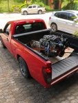
The fun began a few days ago. We used the truck to bring the engine/tranny combo to my friend´s shop where the transplant will take place. This is the last ride under 4 cylinder power
:


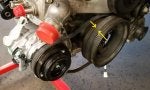
Now here the LS1 we want to swap:


The engine is out of a 1998 F Body. Nothing wrong with it. Ported heads and mild cam by Lloyd Elliott, FAST 92mm Intake and some other upgrades. The F Body just went thru a swap itself and the engine was put on the side just waiting for the transplant into the Colorado. I had been collecting parts for the swap and reading as much as I could in the meantime. I am sure I will encounter a lot of situations where I will need your help guys.

We will be using CP engine mounts and Jamie´s harness with an E40 PCM and 2006 SSR program. That is the main plan.
 
#2 ·
I think the SSR prog is for a 6.0 ?
if that makes a diff in your setup.
diff sensors. LS2 i think.
 
#3 · (Edited)
Thats right. Im doing the programming with HPTuners . Some sensors have been replaced with LS2 sensors (knock and oil pressure and MAF ) I am also using a drive by wire Throttle body from an SSR and the corresponding throttle pedal.

te 4 cylinder is out by now and the engine bay was pressure washed for a fresh new start.


the Ls1 was test fitted in place. For now I found out that I will have to modify my transmission crossmember a little and move it back about two inches. Also the crossmember under the engine will have to be modified in order to clear the Fbody oil pan.
 
#5 · (Edited)
YES love the pics. my donor car is almost apart and hope to follow soon. Just building a frame table and jigging the front/rear suspension incase I want the suspension in the Colorado too.

Quick question...How are you getting around the emissions?
98 into a 2004+
To get a emissions waver in Maryland I have to put at least a 2005 motor in it. (buy vin) and all of its smog equipment.
 

Attachments

#6 ·
Well we have been busy trying to get the engine and transmission sitting in the right place. the engine had to be bolted on to the CP mounts as far to the front of the truck as possible.
None of the T56 shifter provisions line up with the stock position in the cabin.
This is how the T56 looks thru the OEM floor hole.


I really diddnt want to hack the floor up for the shifter, and I wanted an OEM look inside the cabin so after searching for an unavailiable alternative to move the shifter forward to the right position had to build my own. This one is inspired in the SIKKy brand, but they only have shifter relocators to move the shifter even further back. This is what I came up with. We shall see how it performs.

 
#7 ·
that's some great engineering you did man! idk if this is final rendition of your bracket but you may want to consider some form of small dust boot over the original shifter stub to keep dirt out. also I'm not sure how tight that shifter bracket is to the original stub but you may need nylon type washers in-between to keep the action smooth. either way that's a brilliant way to relocate. good job
 
#8 ·
also keisler transmission used to have a kit to move the shifter to the front inspection plate location. theres some other companies that can do the mod for you as well. then youd have to slide the motor and trans further back to get the most from it and it still may be too far forward at that pt.
 
#9 ·
you may want to consider some form of small dust boot over the original shifter stub to keep dirt out.
Thanks for your input CB2004mj, I was considering to do something about that.

Well the swap continues to move in aforward direction and we are solving the Issues we have come across. The engine transmission combo is finally in. The FBody accessories are OK with the exception of the AC compressor. The compressor does not clear the lower control arm mounting bracket. I will have to relocate it to the upper passenger side. This does not seem to be a major problem, because the AC compressor bracket was missng and the compressor too.


This shows the modification necessary to the front lower crossmember so it clears the Fbody oil pan. the crossmember was cut an then boxed using 1/8 sheet steel. ground clearance is excellent. Oil pan does not hang below the crossmember


Here the transmission crossmember in its final location for the T56 mount to line up. All we did was move the crossmember to the rear mount hole on the chassis and added a new piece of 1/4" sheet steel to the front side of the crossmember to line up and bolt to the front hole. The driveshaftt length is perfect for this application.


Finally a view from inside the cabin showing the modified shifter thru the OEM hole in the floor. I plan to use the 5 speed rubber boot there.

 
#10 ·
Thanks for your input CB2004mj, I was considering to do something about that.

Well the swap continues to move in aforward direction and we are solving the Issues we have come across. The engine transmission combo is finally in. The FBody accessories are OK with the exception of the AC compressor. The compressor does not clear the lower control arm mounting bracket. I will have to relocate it to the upper passenger side. This does not seem to be a major problem, because the AC compressor bracket was missng and the compressor too.

View attachment 302889


This shows the modification necessary to the front lower crossmember so it clears the Fbody oil pan. the crossmember was cut an then boxed using 1/8 sheet steel. ground clearance is excellent. Oil pan does not hang below the crossmember

View attachment 302891


Here the transmission crossmember in its final location for the T56 mount to line up. All we did was move the crossmember to the rear mount hole on the chassis and added a new piece of 1/4" sheet steel to the front side of the crossmember to line up and bolt to the front hole. The driveshaftt length is perfect for this application.

View attachment 302893


Finally a view from inside the cabin showing the modified shifter thru the OEM hole in the floor. I plan to use the 5 speed rubber boot there.

View attachment 302895
Thanks for uploading this pic dude, its helped a lot!!

Looking gopod, bet you are itching to drive it :D
 
#12 ·
I am running a NV3500 5 speed. I got the whole truck for the purpose of the driveline and harness. I have heard conflicting opinions on the nv3500 transmissions strength but when the time comes that i Chernobyl the trans i will step up to a t56.
 
#13 ·
Clutch line done too. That was an easy one. I took my OEM clutch line to a hose shop and had them crimp both ends on a 40" length of 3/16" hydraulic hose. This extra length allowed me to re route the hose on top of the transmission into the quick connector on the transmission away from the header collector.
 
#14 · (Edited)
For the harness we are using jamie´s swap harness custom made specifically for this application. I am impressed by the quality of his harness. I also bought the cruise switch and the throttle pedal bracket from him. I hope everything turn out as planned.
In these pictures we were test fitting the harness on the engine before the final install. Everything plugged right in.
E40 PCM / 5.7 LS1 / T56 combo.
 
#15 ·
hmm that cruise switch intrigues me, didn't know Jamie made a specific switch. do you have any more details on just that piece? I'm making my own harness and I was debating on hacking into and splicing the factory stalk or just run a separate switch for cruise. id like to keep it all clean tho without spending 2k on specific stuff lol. my harness has been a little special tho as I deleted all the non-essentials, then added wideband to the egr circuit, flex fuel sensor wired in, swapped injector plugs, deleted O2s, etc etc
 
#16 ·
Sorry, I can´t help you there. I did not get into much detail about the cruise switch.
I dont know exactly what Jamie does to it. He modifies it and sends it to you as a custom cruise switch for the cruise control to work properly.
 
#17 · (Edited)
Got my posi installed and dialed in in the 8.0 axle. I was surprised to find out the pumkin is an aluminum cast. The carrier bearings are the same ones used in the corporate 8.6 axles.
I used a supershim kit for a 8.6 axle too. Fitment was perfect. I am aware this 8.0 axle is a weak link in my drivetrain but I am considering a rear end swap later on. The 8.0 should suffice to start enjoying the ride for now. By the way I have 3.73 gears. I like that ratio with a T56.


Adjusted backlash to what was found before disassembly: .008 and checked contact pattern. Looks good to me.


After that powder coated the cover.

 
#19 ·
Thanks Mark.
Ive been a little busy with work and family but managed to do a little work on some other items.

First I built a benchtop programer for my E40 Pcm that came out really nice and was able to download the stock SSR tune and started changing some of the stuff in there like injector data, removed VATS, got rid of the post cat O2 sensors, etc.

Started with an electrical junction box, added an ALDL connector for the newer vehicles with can bus lines, an E40 J1 connector, an illuminated switch and ended up with this


I then tested it and success!:
 
#21 ·
Repinning of the PCM J1 connector is done! We removed all the wires from their current locations, labeled them and then followed Jamies instructions for the repinning. No real electrical work there, just reposition some wires in new locations, add a few from the new to the cabin harness and make a few splices.


This little fellow here was of great help for the repinning. You dont have to disassemble the whole connector in order to remove the wires. You just remove the pin retainer and insert the tool from the opposite end and pull the wires out.

 
#22 · (Edited)
Cooling system update
Ive also been working on my cooling system setup. I decided to buy a new radiator for several reasons: it was only $ 94 from Rock auto, a new radiator will be as good as it gets and the core of the Denso221-9057 radiator is 1/8" thicker than the OEM radiator.

Well, first problem I found was that the FBody cooling fans wich require a 13" opening for mounting would not fit. The radiator core is not wide enough. I then decided to build custom radiator supports out of 1 1/2" square tube to gain the necessary width for mounting the fans.


Made a custom shroud out of 1/16" stainless steel to accomodate the fans and cut the openings with the plasma gun.


And this is how it turned out in the end:

 
#23 ·
looks great, should flow plenty of air. I have to do something very similar here shortly. been eyeballing some 12" square blade fans off jegs that flow something like 1350 cfm but only take 7.7 amps each. much thinner too but I do like the fbody ones you got. you doing standard rad hoses or making some hard pipe?
 
#24 ·
Those F Body fans draw like 15 amps each. They really move some air.

I am doing standard radiator hoses. I like the OEM look for my swaps.
The lower radiator hose off a 2009 5.3 Colorado is a direct fit (Gates 23437). For the upper hose I used a Gates 20873 wich is a direct fit for the Fbody water pump
 
#26 · (Edited)
Looking good, Ricardo!! You have me wondering about your A/C setup now. You had mentioned in my thread that your accessory drive is set back 3/4", preventing you from using the truck compressor. After you mentioned that, I went to check mine. When I did, I noticed that my accessory drive could be set back that distance, and *not* affect the A/C system at all. I have been trying to tell from your pictures if the A/C portion exists on your pulley. You may be able to use the factory pieces after all...
 

Attachments

#27 ·
Looking good, Ricardo!! You have me wondering about your A/C setup now. You had mentioned in my thread that your accessory drive is set back 3/4", preventing you from using the truck compressor. After you mentioned that, I went to check mine. When I did, I noticed that my accessory drive could be set back that distance, and *not* affect the A/C system at all. I have been trying to tell from you pictures if the A/C portion exists on your pulley. You may be able to use the factory pieces after all...
I’m so jealous of you guys with the a/c. Mine was thrown together on a weekend and I didn’t really bother with it. I should’ve saved some of the stock stuff and tried to mate it with my engine. I was in a hurry and tossed it all.
 
#28 ·
ljk what stock stuff did you toss exactly that you need? I'm gathering parts and have some spares of stuff lol. its all something that can still be installed. I'm making sure the hard parts are there and ill worry about lines and charging the system after the trucks moving
 
#30 ·
I’m pulling the sbc out around spring time and putting a 6.0 ls I have from my s10 in. Once that’s in I’ll work on the a/c but I’ll keep you in mind. I threw away everything so I’ll have to start from scratch. Thanks for the offer.
 
#29 ·
It will all depend on the crank pulley your engine is fitted with. There are basically three different accessory belt offsets from GM:

From left to right:
Corvette CTS-V
Camaro and GTO
Camaro10 up &Truck


There is a 3/4" difference between each of them. I am in the middle, with LS1 Fbody accessories. The AC compressor does not fit with the Camaro bracket.
 
#31 ·
Little update here:
Got the AC sorted out.
I had to use the ICT Billet high passenger side compressor mount for a Sanden 7176 compressor because I am running Camaro accessories and the OEM Canaro compressor will not fit in the lower pass side location. It will interfere with the lower control arm bracket.


Used these No 8 and No 10 male insert o ring adapters for the AC hose ends on the compressor


The Suction side hose compressor end was cut off and a new female o ring hose end with service port fitted to it. The suction hose is size 12 so we welded the no 10 compressor hose end to the barbed section of the no 12 oem hose end to step down.

The high pressure side hose (N8) was done using the OEM aluminum end connection to the condenser and a new female no 8 hose end on the compressor side

 
#32 · (Edited)
After that we continued with the exhaust fabrication. I am using DT headers and want to run an old school H-pipe true dual setup. I am using a Max flow dual 2.5" straight thru SS muffler measuring 5" x 11" x 22" length. This was the largest i found. There is a smaller version with an internal X pipe but I decided to go with this one. I like the old school H pipe sound better.


The muffler was placed in the same location of the OEM muffler to begin with the build. The OEM muffler hangers were cut off the original muffler and welded to the new dual mufler.


Next, the H pipe was built using two SS Tees and fabrication continued to connect with the passenger side header.

 
#36 ·
Thanks Mark. Its been a long journey to get at where it sits today.

I got my heater hoses today, I used Dayco 80416 and Dayco 80405 cut to size hoses for the task. They fit great. Tried ordering the heater hoses for a 2009 V8 colorado from GM and although my order shows "on order" status they have not shipped yet. Its been over a month since I ordered.