Chevrolet Colorado & GMC Canyon Forum banner

AC Compressor Not Kicking On

62K views 47 replies 12 participants last post by  pashaandre  
#1 ·
Forgive my ignorance, my knowledge of AC systems is nothing. This year I went to turn on air conditioning and the air blew warm. Seemed to work fine last year. Noticed the compressor never kicks on at any time. Light on the button lights up, but no audible noise to kick on.

Is this as simple as low refrigerant? What should the pressure be? If any one can give me a few things to check and rule out that would be very helpful.
 
#2 ·
Check the fuse first.

If not, then probably low on refrigerant as you suspect. A reputable local A/C should should be able to get you all set up. However, if you are low on refrigerant, that means you have a leak. You may get by with having them top it off for you only to find it leaks out - at which time you'll need to have them perform a leak detection then replace seals.

The only other thing I can personally think that causes A/C not to work is engine temperature too high. That could be a faulty temperature sensor, but I think you'd have other reasons to think the temperature sensor was faulty.
 
#4 · (Edited)
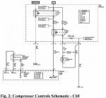
From memory, the circuit to control on/off of the compressor:

The fuse
The AC switch on the dash
the temperature-sensor for interior temperature
the refrigerant pressure-sensor (to detect refrigerant pressure too low or too high)
the relays <---------------------------------------------- edited to add
the BCM

The BCM decides when to switch the compressor on or off based on all the things in that list. This is pretty typical of the AC system on all vehicles these days.

The refrigerant pressure is too low when there is a leak resulting in not enough refrigerant present in the system.
The refrigerant pressure is too high when the compressor is pushing the fluid (refrigerant) harder than the condenser is able to cool and condense it.

Programmed into the BCM is an upper pressure limit and a lower pressure limit.
The actual pressure moment-to-moment must be somewhere between the lower and the upper limits (as measured by that single pressure sensor), else the PCM will not energize the clutch-
..even when it needs to do so to cool the interior.


Other than the sensors and electronics, it's all a matter of the basic physics involved (AC theory).
 
  • Like
Reactions: cusomano
#5 ·
I would also rec. giving a tap on the front of the compressor with a wooden handle of a hammer.(while a/c on max) Clutch clearance can become sticky, make sure the compressor can be turned by hand. (engine OFF) beyond that, like everyone said you need to have the charge level checked out.

DO NOT use a self recharge kit from autoparts stores.
 
#7 ·
Check the 15A IGN Fuse (#23) and the 10A A/C COMP fuse (#77)

Also check the A/C COMP Relay (#50) as well as the A/C Clutch Diode (#65).

There are two wires that feed the A/C Compressor clutch, The dark-green is positive and the black is a ground. You should be able to engage the clutch with a PowerProbe III or similar.
 

Attachments

#8 · (Edited)
You can pull the compressor relay and use a jumper from the battery to the receptacle for the output lead of the relay. Not sure if it is pin 30 or 78. Pin ID is on the bottom of the relay. Don't jam a large object in the relay receptacle as it will stretch it and cause more problems. This would be without the engine running, to check to see if the clutch will "click".

If you can find a set of gages, check the static pressure (system not operating). For ambient temps above 60° the pressure should be at least 50psi. Above 75° it should be 70psi. Both high and low gages should be within 15psi of each other. If the pressure is less that 44psi, the compressor clutch will not engage.
 
#9 ·
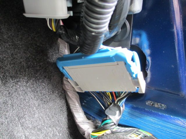
If all fuses check good, pull the passenger side foot panel. And look at the wires associated with the plug. I've seen those connectors fail. The hvac is sending the signal but it's not arriving. I bet that's were the issue is.
 
#10 ·
Swap the a/c relay with another known good one, if it clicks you're getting the request, you wont get the request with under or over charged though.

To verify ckt integrity i suggest then jumping the contact pins from the relay (powering ckt 59 via the relay pin) and make sure the clutch engages (or use a headlamp bulb in the connector) to load test it.

If the a/c relay clicks and the ckt checks ok you have a failed compressor

If the relay doesn't click your easiest least intrusive step is to have charge checked.

Beyond that, I'd need the operation of the pressure switch for this system to see if you could jump it ( I jump fords older fords that way sometimes when I am waiting for the a/c machine at work)
 
#14 ·
The signal from the HVAC Control Module to the BCM goes through connector C203. Dark Green wire with White stripe. C203 can be accessed by dropping the glove box door and looking straight forward. It is a 14 pin connector clipped the the face of the HVAC case. The circuit, same wire color code, also goes through connector C201, located behind the right kick panel.
 
#16 ·
In that connector (C203) the Orange wire is for the Blower high speed. If you jump that wire to ground, with the key on, the blower should operate on high speed.

Cutting and splicing the wires in the C203 connector would only be recommended if there was a problem in the connector, such as corrosion, burned terminals, etc. Have you determined that there is, in fact, a problem with the connector?

You could have a problem internally with the HVAC Control Module, if three of the blower speeds are normal, but high speed is inop.
 
#17 ·
My fan had been cutting out on all speeds. I would open the glove box and squeeze that connector, and it would come back on. It progressed to the point that I would have to really work the wires on both ends of the connector to get it to work. Then finally I could feel something snap. I just figured it was the tan wire. When I cut it from the connector, none of the speeds (1-3) went away, so I figured that was in fact speed 4. But when I butt connected the tans back together, still no speed 4. So you're saying the orange wire is speed 4, what is the tan wire?
 
#19 ·
Hmm. Okay, so I'll try the orange wire to fix the Speed 4 issue, and check the green for the AC.

That connector was made from a cheap nylon, and was prone to overheating. I know several have replaced with one from a Tacoma, and some have just butt-connected all of these wires and done away with the c203.
 
#20 ·
The procedure that I suggested in Post #16 (Jump Orange wire to ground) will not "fix" your problem. If the blower works on high speed, when you connect the Orange wire to a good ground, that means the problem is in the circuit before the connector. What you would be doing, in effect, is bypassing the switch in the HVAC Module. The Orange wire goes to the blower switch in the HVAC module which should be connecting the circuit to ground when high speed is selected.
 
#21 ·
Hey RICK_CREW! In an earlier post regarding this you wrote "The fan continues to run on speed 4 because that's the highest speed and high speed doesn't use the resistor at all.
So setting the switch to speed 4 bypasses the resistors to let the fan run at it's highest speed.

This is a simple problem but a real pain in the ass.
And it eventually happens to every first-generation 355 model.

I repaired mine with just a few inches of 16-gauge wire and a soldering iron.
I just bypassed the connector, "jumpering" around it.
That was 7 years ago and it's fine.

Other members here report good results with the GM repair kit."

Did you jump all the wires, or just the wire for high speed? My AC clutch still is not engaging, and my low side pressure is in the green. I may or may not have a refrigerant issue, but IIRC the AC was working fine before the c203 connector went tits up. If I jump the green/white wire, could that make my clutch engage? I checked the fuses and relays and they're good.
 
#22 ·
You seem to be working two problems at the same time. Did you ever figure out the cause of the blower high speed issue?

When A/C is selected on the HVAC Control Module, the switch sends a signal to the BCM, which in turn tells the PCM to turn on the compressor. That signal from the A/C selector switch to the BCM goes through the Evaporator Temperature Sensor.

Now, the BCM monitors the temperature sensor and will not allow operation of the compressor if the temp is below 32°.

If the wiring to/from the temp sensor is defective it could cause the BCM to prevent the PCM from turning on the compressor.

This is where connector C203 may be related. The signal going from the HVAC Control Module to the Temp Sensor is the Light Green wire. The signal going from the Temp Sensor to the BCM is the Dark Green wire with White stripe. The Black wire is the ground for the Temp Sensor.

Bottom line: at connector C203, check the condition of the connections at those three wires.
 
#23 ·
Let me see if I can beat this horse once more. Does anyone know if the wires in the c203 connector share grounds, or are they simple blue to blue, orange to orange, brown to brown? I really feel the connector is my problem, as now all fan speeds are dropping out, and all I have to do is keep my glove box door dropped, and bend the connector a little in my hand and everything comes back on. It gets hot as Mississippi, as it should as it is a resistor. Still no speed 4, so I'm wondering if that's the bad connection that's shutting everything else off. I have already cut and butt-connected the tan wire, which I'm told in a post above this that is the speed 2 wire. That is what makes me wonder if there is a common ground in there somewhere that they all need to feed through. Otherwise, wouldn't my speed 2 always work?

Is the c203 connector essential, or can it be junked and just connect the wires together by color?
 
#24 · (Edited)
I think you are confused regarding the configuration of that connector. It is an inline connector, probably configured at that location for ease of installation. Notice that each colored wire goes in one side and exits thee same color, at the same position on the other side. The connector could be eliminated without changing the way the circuits work. The only ground wire in that connector (Black) is the ground for the Evaporator Temp Sensor. When you disconnect C203, what condition are the terminals in? Do they appear burned/overheated?

You might want to expand your search a bit and check the condition of the terminals/wires in connector C201, which is located behind the right kick panel. Both the power side of the HVAC system circuit and the ground side, go through that connector. There have been reports of burned pins in that connector also.

 
#26 ·
Okay, now I understand. You can certainly cut all of the wires. match them by color and bypass the connector. Another option, which is rather expensive, is to replace the connector with a "Service" connector. That is a connector that comes with pigtail wires to splice into the existing harness. The two halves of the connector would cost about $60.

While there isn't any ground wire in that connector for the blower, the power wires for all speeds are there. The Yellow wire is low speed, the Tan wire is speed 2, the Light Blue Wire is speed 3 and the Orange wire is high speed. The wires for speeds 1/2/3 are coming from the resistor module and going to the blower switch in the Control Panel. The Orange wire bypasses the resistor module, but after going through C203, it also goes to the blower switch.

Just a note: The Brown wire is the power lead to the blower. Will have 12 volts with key in ACC or RUN.
 
#28 ·
That is a kind of confusing question. The Blower Resistor Module located in the bottom of the HVAC case is what provides the resistance for the three lower blower speeds. We haven't discussed the connector for the Blower Resistor Module. I assumed that all other connectors, except the 10 wire connector C203, were connected and presumed okay. Connector C203 provides no resistance, of any kind, for any of the circuits involved.

I am assuming that we have been discussing problems with the 10 wire connector C203) mounted to the face of the HVAC case. If not, then we will probably have to start over at the beginning. If the 4 wire connector for the Blower Resistor Module is attached and secure the fan speeds should not be affected by removing C203. I say "should" because it would depend on the quality of the spliced wire connections.
 
#30 ·
I have a 05 colorado AC compressor not kicking on. I am gonna be checking some sensors tonight that I have read to check in this thread. The temp sensor behind glove box I have read to jump the dark green and light green wires. The hi/low pressure sensor out by firewall has 3 wires, a red, grey, and black. Does anyone know which one of these to jump to make it work.