
Disclaimer
The community here at 355nation.net urges you to please use caution and seek professional assistance when performing modifications to your vehicle. Before attempting any modification it is advised that you refer to your Colorado or Canyon service manual or contact a certified mechanic as not all GMT355 trucks are the same. The staff and the associated members are in no way responsible for any damages, injuries or other harm inflicted to your vehicle or yourself which may result in attempting these modifications. The posts and content presented on this site reflect in no way the views of 355nation.net or it’s ownership.
![Image]()
A 355nation How To presented by
colbyjohnson1994
Project Name
Install an Aftermarket Alarm/Remote Start System
Project Description
Installing a remote start allows you to start your vehicle to either warm up your engine when it is cold, or cool down the vehicle on a hot day. There are a large range of devices and systems to choose from that will allow you to expand control other devices on your vehicle at the push of a button.
Almost every year is a little different, but we will try to cover all of them as best we can to provide a central How To for all years of the 1st gen Colorados/Canyons.
Skill Level
Moderate-Advanced
Project Vehicle
Make: GMC
Model: Canyon
Year: 2005
Engine: 3.5L
Power windows: Yes
Sun Roof: No
VATS (Passlock): disabled (HPTuners)
Tools Needed
[Needed]
Wire Strippers
Electrical Tape
Looming [Optional]
Phillips Screwdriver
Zip-Ties
[1st Option, Recommended]
Soldering Iron
Solder
Razor Blade
[2nd Option, Less Longevity]
T-Taps (18-22 AWG)
Insulated Spade Connectors (18-22 AWG)
Pliers
Project Time
2 or more hours
Project Cost
I paid $104 on Amazon
Remote Start System - Price Varies $50-400
Bypass Module - DB-ALL - Price Varies
***DO NOT GO CHEAP ON THE BYPASS MODULE***
If the Bypass module fails your immobilizer could disable your vehicle
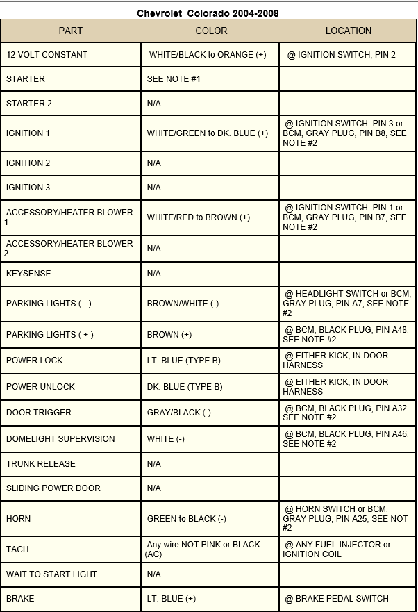
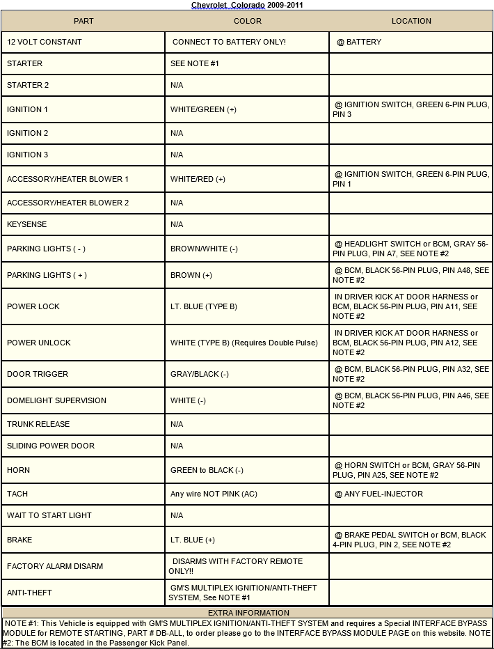
Here are wiring diagrams for the 2004-2008 and 2009-2011 model years:
I bought an Avital 5303L. It comes with a one page description of all wires, and a manual to use the remote (needed). The wire color codes I will be using will reflect similar Directed products.
Good brand recommendations
NOT recommended
Good mounting locations for Alarm Boxes
Slide driver seat back, remove the plastic door sill, followed by the driver side kick panel. The floor sill has 3 panel clips on the exterior side of the door frame and can be easily removed by carefully prying on the interior side starting at the edges. The kick panel can be removed by pulling on the corner point towards the front of the vehicle. The 1 panel clip will pop out and you will be able to slide the panel towards you. Repeat for the passenger side, which will expose the Body Control Module.
Next you will need to remove the emergency brake panel. Remove the one phillips screw on the side, and then remove two more phillips screws holding the hood release on. Lay on the floor and trace your emergency brake cable to the emergency brake release. Pull on the release with your hand, and with the other hand unhook the cable.


I found it easier to work with the carpets peeled back, so you can do this if it helps you as well.
The rest of this will be in sections:
1. Inputs from Sensors (Hood, Doors, Valet button)
2. Output for Actuators (Door locks, Siren, Security Light)
3. Remote Start (The grande finale)
FOR ALL SECTIONS:
USE YOUR DESIRED METHOD OF CONNECTING WIRES
Start by getting power in to your cab. Use a minimum of 8 AWG wire, with a 30 AMP fuse. This is how I ran mine, there are many options on getting power to the cab. Leave it unhooked from the battery until everything else is finished.


1. Inputs from Sensors
Starting with door triggers. Our doors are grounded when opened and positive when closed. We will need to use the negative trigger wire from the system we are installing. The wires we are looking for are found easiest in the passenger side connected to the BCM.


We will be looking at the gray connector to find our wires, according to wire color sheet to your designated year. If you want all doors connected to this trigger you will need to diode isolate each door trigger. Use this picture to help you:

Next we will be wiring up the Brake sense. Go to the driver side. Above your brake pedal you will see a two wire connector, with one wire being Light Blue. This will be the brake sense/shutdown wire to hook up.
If you plan on using the included Shock Sensor, Proximity, etc. now would be a good time to hook those up.
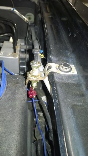
Find a place under the hood to mount the Hood sensor, and feed the wire back in to the cab using the same place as your power wire. Here is my location with a cheesy bracket.
If your alarm system has remote start, you will find that you have a neutral safety switch wire to hookup. Ground it with your Alarm box ground. It is not needed, because the starter relay will not have positive power without it being in Neutral/Park anyways. The PCM triggers the ground side of the relay for starting, which is triggered by the BCM.
Good Locations for Valet Button/Security LED
2. Output to Actuators
Since we are already on the drivers side, now is a good time to hook up Park Lights, Dome Light Supervision, and Siren.
Remove the 9/32" screw located below the headlight/dimmer switch. Push on the bottom of the switch and it will go back into the dash. Reach up from underneath and hold it upright to unhook the green connector from the backside. This harness will contain two wires we need: park lights (-) and domelight supervision. They are color coded based on the diagram for your vehicle.
***NOTE: YOU WILL NEED TO SET THE PARKING LIGHT OUTPUT TO (-) NEGATIVE ON YOUR ALARM SYSTEM BOX. IT IS USUALLY SET BY A JUMPER PIN***
Mount the siren under your hood somewhere, and hook it up to you horn output of your alarm system.
Good Locations:
3. Remote Start
The starting system on our trucks works by detecting inputs from the ignition switch.
Off Position - Accessory off, Run off -> Give power to nothing - RAP taking over
Accessory Position - Accessory On, but not Run -> Give power to Accessory circuit
Run Position - Accessory On, Run On -> Give power to both Accessory and "Running" Circuits
Start Position - Accessory Off, Run On -> Send Start Enable signal to PCM to start vehicle, while not giving power to the Accessory Circuit (hence, why your radio shuts off while starting)
The remote start wires are located based on your wiring chart. For 2004-2008 models you will need to go on the passenger side to access the Gray plug on your BCM. For 2009+ models you will need to be at the 6 PIN Green harness located under your steering column. Hookup the ignition 1 and accessory wires according to your wiring diagram.
You will NOT need
For 2004-2008 models:
THERE ARE TWO pairs of blue and brown wires. Pick the pair that is up near the top as pictured (four wires at top of connector are the correct wires to chose from):


Now it is time to hook up the power wire you ran at the beginning to the fused power wires on the remote start module, and the power wire(s) from the alarm box.
Connect the main power line to the battery and begin testing!
Finished Product (it's a video)
The community here at 355nation.net urges you to please use caution and seek professional assistance when performing modifications to your vehicle. Before attempting any modification it is advised that you refer to your Colorado or Canyon service manual or contact a certified mechanic as not all GMT355 trucks are the same. The staff and the associated members are in no way responsible for any damages, injuries or other harm inflicted to your vehicle or yourself which may result in attempting these modifications. The posts and content presented on this site reflect in no way the views of 355nation.net or it’s ownership.
A 355nation How To presented by
colbyjohnson1994
Project Name
Install an Aftermarket Alarm/Remote Start System
Project Description
Installing a remote start allows you to start your vehicle to either warm up your engine when it is cold, or cool down the vehicle on a hot day. There are a large range of devices and systems to choose from that will allow you to expand control other devices on your vehicle at the push of a button.
Almost every year is a little different, but we will try to cover all of them as best we can to provide a central How To for all years of the 1st gen Colorados/Canyons.
Skill Level
Moderate-Advanced
Project Vehicle
Make: GMC
Model: Canyon
Year: 2005
Engine: 3.5L
Power windows: Yes
Sun Roof: No
VATS (Passlock): disabled (HPTuners)
Tools Needed
[Needed]
Wire Strippers
Electrical Tape
Looming [Optional]
Phillips Screwdriver
Zip-Ties
[1st Option, Recommended]
Soldering Iron
Solder
Razor Blade
[2nd Option, Less Longevity]
T-Taps (18-22 AWG)
Insulated Spade Connectors (18-22 AWG)
Pliers
Project Time
2 or more hours
Project Cost
I paid $104 on Amazon
Remote Start System - Price Varies $50-400
Bypass Module - DB-ALL - Price Varies
***DO NOT GO CHEAP ON THE BYPASS MODULE***
If the Bypass module fails your immobilizer could disable your vehicle
Here are wiring diagrams for the 2004-2008 and 2009-2011 model years:
I bought an Avital 5303L. It comes with a one page description of all wires, and a manual to use the remote (needed). The wire color codes I will be using will reflect similar Directed products.
Good brand recommendations
- Avital - high end models use Directed boxes
- Audiovox
- Viper
- Directed - They make lots of good products
NOT recommended
- Clifford (previous owner chose this, caused parasitic drain from failed security box. Absolutely no support for products)
Good mounting locations for Alarm Boxes
- Underneath A/C Controls behind dash (where I did)
- Behind glove box
- Behind parking brake release panel (where the previous owner put my old system)
Slide driver seat back, remove the plastic door sill, followed by the driver side kick panel. The floor sill has 3 panel clips on the exterior side of the door frame and can be easily removed by carefully prying on the interior side starting at the edges. The kick panel can be removed by pulling on the corner point towards the front of the vehicle. The 1 panel clip will pop out and you will be able to slide the panel towards you. Repeat for the passenger side, which will expose the Body Control Module.
Next you will need to remove the emergency brake panel. Remove the one phillips screw on the side, and then remove two more phillips screws holding the hood release on. Lay on the floor and trace your emergency brake cable to the emergency brake release. Pull on the release with your hand, and with the other hand unhook the cable.
I found it easier to work with the carpets peeled back, so you can do this if it helps you as well.
The rest of this will be in sections:
1. Inputs from Sensors (Hood, Doors, Valet button)
2. Output for Actuators (Door locks, Siren, Security Light)
3. Remote Start (The grande finale)
FOR ALL SECTIONS:
USE YOUR DESIRED METHOD OF CONNECTING WIRES
Start by getting power in to your cab. Use a minimum of 8 AWG wire, with a 30 AMP fuse. This is how I ran mine, there are many options on getting power to the cab. Leave it unhooked from the battery until everything else is finished.
1. Inputs from Sensors
Starting with door triggers. Our doors are grounded when opened and positive when closed. We will need to use the negative trigger wire from the system we are installing. The wires we are looking for are found easiest in the passenger side connected to the BCM.
We will be looking at the gray connector to find our wires, according to wire color sheet to your designated year. If you want all doors connected to this trigger you will need to diode isolate each door trigger. Use this picture to help you:
Next we will be wiring up the Brake sense. Go to the driver side. Above your brake pedal you will see a two wire connector, with one wire being Light Blue. This will be the brake sense/shutdown wire to hook up.
If you plan on using the included Shock Sensor, Proximity, etc. now would be a good time to hook those up.
Find a place under the hood to mount the Hood sensor, and feed the wire back in to the cab using the same place as your power wire. Here is my location with a cheesy bracket.
If your alarm system has remote start, you will find that you have a neutral safety switch wire to hookup. Ground it with your Alarm box ground. It is not needed, because the starter relay will not have positive power without it being in Neutral/Park anyways. The PCM triggers the ground side of the relay for starting, which is triggered by the BCM.
Good Locations for Valet Button/Security LED
- Driver side kick panel
- Center console
- Stereo dash bezel
2. Output to Actuators
Since we are already on the drivers side, now is a good time to hook up Park Lights, Dome Light Supervision, and Siren.
Remove the 9/32" screw located below the headlight/dimmer switch. Push on the bottom of the switch and it will go back into the dash. Reach up from underneath and hold it upright to unhook the green connector from the backside. This harness will contain two wires we need: park lights (-) and domelight supervision. They are color coded based on the diagram for your vehicle.
***NOTE: YOU WILL NEED TO SET THE PARKING LIGHT OUTPUT TO (-) NEGATIVE ON YOUR ALARM SYSTEM BOX. IT IS USUALLY SET BY A JUMPER PIN***
Mount the siren under your hood somewhere, and hook it up to you horn output of your alarm system.
Good Locations:
- Behind battery box, by ABS module
- Behind grille
3. Remote Start
The starting system on our trucks works by detecting inputs from the ignition switch.
Off Position - Accessory off, Run off -> Give power to nothing - RAP taking over
Accessory Position - Accessory On, but not Run -> Give power to Accessory circuit
Run Position - Accessory On, Run On -> Give power to both Accessory and "Running" Circuits
Start Position - Accessory Off, Run On -> Send Start Enable signal to PCM to start vehicle, while not giving power to the Accessory Circuit (hence, why your radio shuts off while starting)
The remote start wires are located based on your wiring chart. For 2004-2008 models you will need to go on the passenger side to access the Gray plug on your BCM. For 2009+ models you will need to be at the 6 PIN Green harness located under your steering column. Hookup the ignition 1 and accessory wires according to your wiring diagram.
You will NOT need
- Output to Start
- Input from Start
- Accessory 2
- Ignition 2 or 3
For 2004-2008 models:
THERE ARE TWO pairs of blue and brown wires. Pick the pair that is up near the top as pictured (four wires at top of connector are the correct wires to chose from):
Now it is time to hook up the power wire you ran at the beginning to the fused power wires on the remote start module, and the power wire(s) from the alarm box.
Connect the main power line to the battery and begin testing!
Finished Product
(it's a video)